
Welding Ceramics For Clean, Consistent Stranded Wire Welds
Welding stranded wire cleanly is one of the most technically demanding challenges in butt welding. Micro-Weld ceramic sleeves give stranded material the firm, even support it needs to weld together cleanly — every time, at every gauge.
Why Stranded Wire Is Harder To Weld Than Solid
Solid wire and rod sit uniformly in the weld zone — the machine clamps, heats, and upsets with predictable results. Stranded wire is different. Individual conductors want to spread under clamping pressure, migrate during heating, and resist the uniform upset needed for a clean, strong weld joint.
Without the right support, you get uneven conductor distribution, off-center upsets, weak weld zones, and frequent weld breaks — especially at finer gauges where individual strands are thinner and more prone to movement.
| Micro-Weld ceramic sleeves solve this by containing the stranded bundle throughout the weld cycle — constraining the conductors during upset so the weld forms cleanly across the full cross-section of the wire. “Getting a clean, firm hold when welding stranded material is challenging. Our ceramics ensure stranded material is securely and evenly welded together, providing a clean, strong hold every time.” |
What Happens Without Proper Ceramic Weld Backing
These are the weld quality issues most commonly reported by production teams running stranded wire on butt welders without ceramic sleeve support.
Conductor Spread And Separation
Individual strands fan out under clamping pressure, creating gaps in the weld face and producing a weak, uneven joint that fails under tension.
Incomplete Upset Formation
Without lateral containment, the upset flash migrates outward instead of consolidating at the weld face. The result looks like a weld but lacks the strength of one.
Inconsistent Weld Quality Across Gauges
Finer gauge stranded wire is more susceptible to movement — so results vary not just between runs, but within the same production batch.
Increased Weld Breaks And Downtime
Poor weld integrity in stranded wire shows up as weld breaks during downstream processing — tension tests, coiling, or in-service load — causing costly line stoppages.
Micro-Weld ceramic weld backing eliminates all four failure modes by providing precise dimensional support to the stranded bundle throughout the entire weld cycle — heat, upset, and cool-down.
How Ceramic Sleeves Support The Weld Cycle
Micro-Weld ceramic sleeves function as precision-matched containment for the stranded wire bundle during butt welding. Here’s what happens at each stage.
1. Load & Clamp
The ceramic sleeve is placed around the stranded wire ends at the weld zone. Its inner diameter is matched precisely to the wire gauge, constraining the individual conductors as clamping force is applied.
2. Heat & Upset
As weld current passes through the joint and the machine applies upset force, the ceramic backing maintains the conductor bundle geometry — preventing strand spread and ensuring the upset consolidates at the weld face.
3. Release & Inspect
Once the weld cycle is complete and the joint has cooled, the ceramic sleeve is removed. What remains is a clean, uniform weld zone with consistent upset and full cross-sectional contact across all strands.
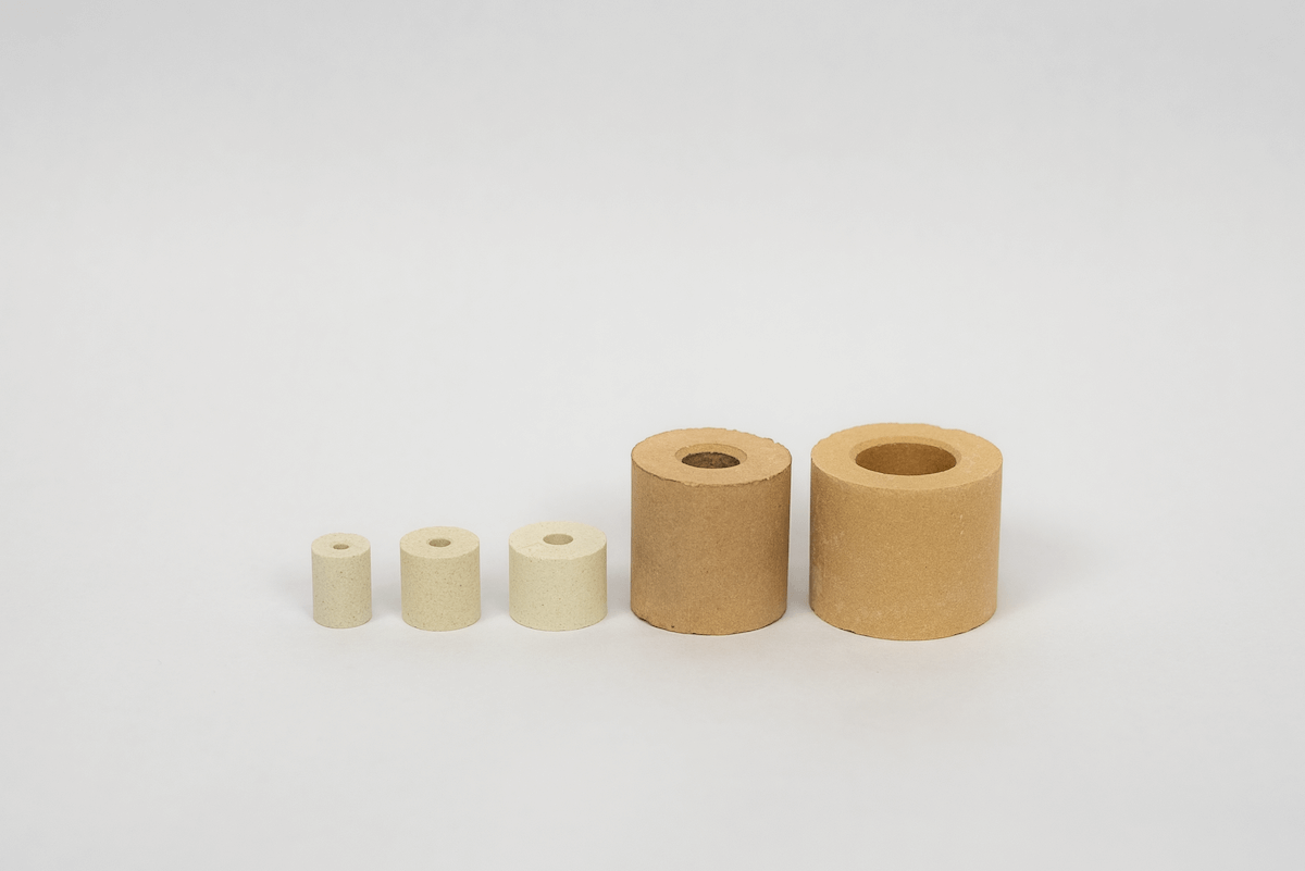
Ceramic Sleeve Specifications
Micro-Weld ceramic sleeves are available in standard and tight-tolerance configurations across a wide gauge range, with compatibility for the GP-0, GP-1, GP-2, and GP-3 welder platforms. Select your welder below.
All dimensions in decimal inches unless noted. Full spec sheet available as a PDF download. Contact our team for custom gauge or OD requirements.
GP-1 / GP-2 / GP-3 – Standard
| Part no. | Gauge | ID range | OD range | Length | ID (mm) |
| 58321 | 24 GA | .021″ – .025″ | .368″ – .378″ | .500″ – .515″ | 0.53 – 0.64 mm |
| 58312 | 20 GA | .044″ – .052″ | .368″ – .378″ | .500″ – .515″ | 1.12 – 1.32 mm |
| 58313 | 19 GA | .048″ – .052″ | .368″ – .378″ | .500″ – .515″ | 1.12 – 1.32 mm |
| 58311 | 18 GA | .053″ – .061″ | .368″ – .378″ | .500″ – .515″ | 1.35 – 1.55 mm |
| 58310 | 17 GA | .056″ – .064″ | .368″ – .378″ | .500″ – .515″ | 1.42 – 1.63 mm |
| 58309 | 16 GA | .065″ – .073″ | .368″ – .378″ | .500″ – .515″ | 1.65 – 1.85 mm |
| 58308 | 14 GA | .079″ – .089″ | .368″ – .378″ | .500″ – .515″ | 2.01 – 2.26 mm |
| 58307 | 13 GA | .086″ – .096″ | .368″ – .378″ | .500″ – .515″ | 2.18 – 2.44 mm |
| 58306 | 12 GA | .098″ – .108″ | .368″ – .378″ | .500″ – .515″ | 2.49 – 2.74 mm |
| 58305 | 11 GA | .107″ – .122″ | .348″ – .378″ | .500″ – .515″ | 2.72 – 3.10 mm |
| 58304 | 10 GA | .121″ – .131″ | .368″ – .378″ | .500″ – .515″ | 3.07 – 3.33 mm |
| 58303 | 9 GA | .133″ – .143″ | .490″ – .500″ | .500″ – .515″ | 3.38 – 3.63 mm |
| 58302 | 8 GA | .149″ – .159″ | .490″ – .500″ | .500″ – .515″ | 3.78 – 4.04 mm |
| 58301 | 6 GA | .185″ – .195″ | .620″ – .630″ | .500″ – .515″ | 4.69 – 4.93 mm |
| 58300 | 4 GA | .235″ – .245″ | .740″ – .750″ | .480″ – .520″ | 5.97 – 6.22 mm |
GP-1 / GP-2 / GP-3 – Tight-ID
| Part no. | Gauge | ID range | OD range | Length | ID (mm) |
| 58324 | 22-A GA | .030″ – .036″ | .363″ – .393″ | .500″ – .515″ | 0.76 – 0.91 mm |
| 58382 | 22 GA | .032″ – .038″ | .220″ – .280″ | .365″ – .385″ | 0.81 – 0.97 mm |
| 58314 | 20-A GA | .043″ – .047″ | .368″ – .378″ | .500″ – .515″ | 1.09 – 1.19 mm |
| 58323 | 14-A GA | .074″ – .078″ | .373″ – .383″ | .500″ – .515″ | 1.88 – 1.98 mm |
| 58322 | 7 GA | .152″ – .156″ | .490″ – .500″ | .500″ – .515″ | 3.86 – 3.96 mm |
GP-0
| Part no. | Gauge | ID range | OD | Length |
| 58388 | 18 GA-GP-0 | .056″ – .060″ | .093″ | .203″ |
| 58332 | 20 GA-GP-0 | .036″ – .042″ | .093″ | .203″ |
| 58331 | 22.5 GA-GP-0 | .034″ – .038″ | .093″ | .203″ |
| 58326 | 22 GA-GP-0 | .028″ – .032″ | .062″ | .203″ |
| 58327 | 24 GA-GP-0 | .029″ – .031″ | .093″ | .203″ |
| 58342 | 26 GA-GP-0 | .019″ – .021″ | .062″ | .203″ |
Full dimensional specifications and tolerance tables available in our ceramics brochure PDF.
What Micro-Weld Ceramic Weld Backing Delivers
Switching from improvised stranded wire support to precision-matched ceramic sleeves has measurable effects on weld quality, consistency, and downstream yield.
Clean, uniform weld face
Ceramic containment ensures the upset forms evenly across the full wire cross-section — no voids, no spread conductors, no partial fusion.
Consistent results across gauges
Each ceramic sleeve is dimensionally matched to a specific gauge range. The same quality and process control applies at 24 GA as it does at 4 GA.
Reduced weld breaks
Stronger, more consistent weld zones mean fewer breaks during downstream tension testing, coiling, and in-service load — fewer stoppages, less rework.
Faster cycle times
Predictable weld formation means fewer rejected welds and less time spent diagnosing quality issues. Your line moves faster when every weld is right the first time.
High-temperature stability
Ceramic material withstands the thermal demands of the weld cycle without deforming — maintaining dimensional accuracy from the first weld to the last in a run.
Designed for Micro-Weld machines
These ceramics are engineered specifically for Micro-Weld GP-0, GP-1, GP-2, and GP-3 platforms — not generic filler products that happen to fit.
Ceramic Sleeve vs. Other Weld Backing Approaches
Not all ceramic backing for welding is the same. Here’s how Micro-Weld precision ceramic sleeves compare to the alternatives teams typically try before switching.
| Feature | Micro-Weld ceramic sleeve | Generic ceramic backing tape | No backing / improvised support |
| Gauge-specific fit | Yes — precision-matched ID per gauge | No — flat tape, not contoured to round wire | No |
| Conductor containment during upset | Full 360° containment | Partial — backing only, no lateral support | None |
| Reusable | Yes | No — single-use tape | N/A |
| Machine compatibility | GP-0, GP-1, GP-2, GP-3 | General purpose — not machine-matched | N/A |
| Weld consistency | High | Variable | Low |
| Suitable for fine gauge (20–26 GA) | Yes | Limited | Not recommended |
Frequently asked questions
Welding ceramics is a broad term for ceramic materials used to support or back a weld joint during the welding cycle. Ceramic weld backing tape is a flat, adhesive-backed ceramic strip used mainly in groove and fillet welds to support the root pass on the back side of a joint. Micro-Weld ceramic sleeves are a different form factor — tubular, precision-ID components that fully encircle the wire bundle at the weld point, providing 360° containment during the butt weld cycle. They’re purpose-built for stranded wire butt welding rather than structural joint welding.
Yes — the ceramic sleeve must be matched to the wire gauge being welded. Each sleeve has a specific inner diameter tolerance range designed for a particular gauge. Using a sleeve with too large an ID allows conductor movement and defeats the purpose; too small and it won’t clear the wire. Our part number table covers gauges from 4 GA down to 24 GA (and 26 GA for GP-0 machines). If you’re running multiple gauges, you’ll need the corresponding sleeve for each.
Our ceramic sleeves are engineered specifically for Micro-Weld GP-0, GP-1, GP-2, and GP-3 platforms, with outer diameter and length specifications matched to those machines’ weld heads and clamp geometry. If you’re running a different machine, the OD and length may not align correctly. Contact our team and we can discuss whether standard sizes would work for your application, or whether a custom configuration is needed.
Micro-Weld ceramic sleeves are reusable, provided they’re inspected after each use for cracking, chipping, or dimensional wear. Unlike single-use ceramic weld backing tape, the sleeves are designed to be removed cleanly after the weld cycle and reused across multiple welds. Service life depends on the wire material, weld temperature, and cycle frequency. Our team can advise on inspection intervals based on your production volume.
Start with the wire gauge you’re welding and your machine platform (GP-0 vs. GP-1/2/3). Then cross-reference the spec table above to find the part number with the appropriate ID range for your wire diameter. If your wire diameter falls between two listed gauges, or if you need tighter tolerances than our standard range, contact our team directly — we can recommend the right fit or advise on tight-ID alternatives from the same product line.